olo_base_decode_firstbit
Status Information
VHDL Source: olo_base_decode_firstbit
Description
This entity implements a first-bit decoder. It does return the index of the lowest bit set in a vector.
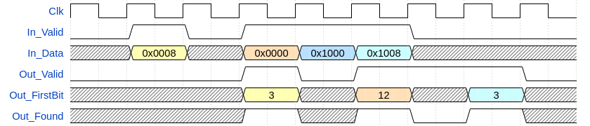
First bit decoding can be done in only a few lines of code if all the decoding is done in one clock cycles. However, for doing first-bit decoding on very wide vectors this leads to poor timing performance. In this case using olo_base_decode_firstbit makes sense - because it allows pipelining the operation.
The figure below assumes InReg_g=false, OutReg_g=false and PlRegs_g=2.
Generics
| Name | Type | Default | Description |
|---|---|---|---|
| InWidth_g | positive | - | Width of the input vector |
| InReg_g | boolean | true | If set to true all inputs are registered before any operations are done on it. Can be set to false if the user knows that *_In_Data is driven by FFs directly without combinatorial logic after the FF. |
| OutReg_g | boolean | true | If set to true all outputs are registered. Can be set to false if the user knows that Out_FirstBit and Out_Found are fed into FFs without any combinatorial logic. |
| PlRegs_g | natural | 1 | Number of pipeline registers in the first-bit decoding logic. 0 Means that the decoding is done in one clock-cycle, 1 means that one register stage is added and the logic is split into two clock cycles. Range: 0 ... ceil(log2(InWidth_g))/2-1 |
Interfaces
Control
| Name | In/Out | Length | Default | Description |
|---|---|---|---|---|
| Clk | in | 1 | - | Clock |
| Rst | in | 1 | - | Reset input (high-active, synchronous to Clk) |
Input Data
| Name | In/Out | Length | Default | Description |
|---|---|---|---|---|
| In_Data | in | InWidth_g | - | Input data vector |
| In_Valid | in | 1 | '1' | AXI4-Stream handshaking signal for In_Data |
Output Data
| Name | In/Out | Length | Default | Description |
|---|---|---|---|---|
| Out_FirstBit | out | ceil(log2(InWidth_g)) | N/A | Index of the lowest bit set in In_Data |
| Out_Found | out | 1 | N/A | Set to '1' if any bit in In_Data was set. If no bit is set in In_Data this output is '0'. |
| Out_Valid | out | 1 | N/A | AXI4-Stream handshaking signal for Out..._ |
Architecture
Below figure shows the overall architecture of the block. The figure assumes InReg_g=true, OutReg_g=true and PlRegs_g=2.
Note that these settings are chosen for illustrative reasons only. Two pipeline registers for only a 64 bit first-bit detector would not actually be required.

The first stage detects the index of the first bit on a small number of input bits. All subsequent stages detect the upstream stage with the lowest index that found a bit, forward this result to the output and extend a few more bits of the index information.