olo_ft_ecc_monitor_axi
Status Information
VHDL Source: olo_ft_ecc_monitor_axi
Description
This component wraps the olo_ft_ecc_monitor EDAC monitor with an AXI4-Lite register interface (32-bit data width) and an interrupt output. It is the drop-in housekeeping block: connect the SEC/DED flags of the ft instances, attach the AXI4-Lite port to the system bus, and software gets per-channel error counters and event interrupts through the register map below.
Generics
| Name | Type | Default | Description |
|---|---|---|---|
| Channels_g | positive | - | Number of monitored channels (range 1 to 255), see olo_ft_ecc_monitor. |
| CounterWidth_g | positive | 16 | Counter width (range 1 to 16), see olo_ft_ecc_monitor. |
| AxiAddrWidth_g | positive | 12 | AXI4-Lite address width (range 6 to 30). Must satisfy 2^AxiAddrWidth_g >= 0x10 + 4 * Channels_g (checked by an elaboration assert); the default of 12 covers the maximum channel count. |
| ReadTimeoutClks_g | positive | 100 | Read timeout of the wrapped olo_axi_lite_slave. Reads of unmapped addresses are answered through this timeout with an error response. |
Interfaces
Control
| Name | In/Out | Length | Default | Description |
|---|---|---|---|---|
| Clk | in | 1 | - | Clock |
| Rst | in | 1 | - | Reset (high-active, synchronous to Clk) |
AXI4-Lite
The full AXI4-Lite slave interface (S_AxiLite_*) with 32-bit data width, identical in behavior to
olo_axi_lite_slave. Write byte enables are ignored (whole-word
register accesses only).
Event Inputs
| Name | In/Out | Length | Default | Description |
|---|---|---|---|---|
| In_EccSec | in | Channels_g | - | SEC indication per channel. |
| In_EccDed | in | Channels_g | - | DED indication per channel. |
| In_Valid | in | Channels_g | all '1' | Qualifier per channel, see olo_ft_ecc_monitor - Connecting Sources. |
Interrupt
| Name | In/Out | Length | Default | Description |
|---|---|---|---|---|
| Irq | out | 1 | N/A | Registered level interrupt: high while any IRQ_STATUS bit with its IRQ_ENA bit set is pending. Deasserts when the pending bits are cleared (write-one-to-clear) or masked. |
Register Map
All registers are 32-bit words; the layout is fixed and independent of the generics. Unused bits
read as zero. The counter block occupies 0x10 to 0x10 + 4 * (Channels_g - 1); all addresses
above it are unmapped.
| Offset | Name | Access | Content |
|---|---|---|---|
| 0x00 | INFO | RO | [7:0] Channels_g, [12:8] CounterWidth_g (software discovery) |
| 0x04 | CTRL | WO | Bit 0: CLR_ALL. Writing '1' clears all counters. Reads as zero. |
| 0x08 | IRQ_STATUS | R / W1C | Bit 0: a SEC event was counted, bit 1: a DED event was counted (since the last clear). Write '1' to clear a bit; a hardware set in the same cycle wins over the clear. |
| 0x0C | IRQ_ENA | RW | Bit 0/1: interrupt enable mask for the IRQ_STATUS bits. Reset to zero (masked). |
| 0x10 + 4 * ch | CNT_ch | RO / write=clear | [15:0] SEC counter, [31:16] DED counter of channel ch = 0 to Channels_g - 1 (zero-extended when CounterWidth_g < 16). Any write clears the channel atomically; an event arriving in the same cycle survives the clear. |
Reads of unmapped addresses are not acknowledged and are answered by the olo_axi_lite_slave read timeout with an error response. Writes to read-only or unmapped addresses are ignored (the write response is OKAY).
Detailed Description
Architecture
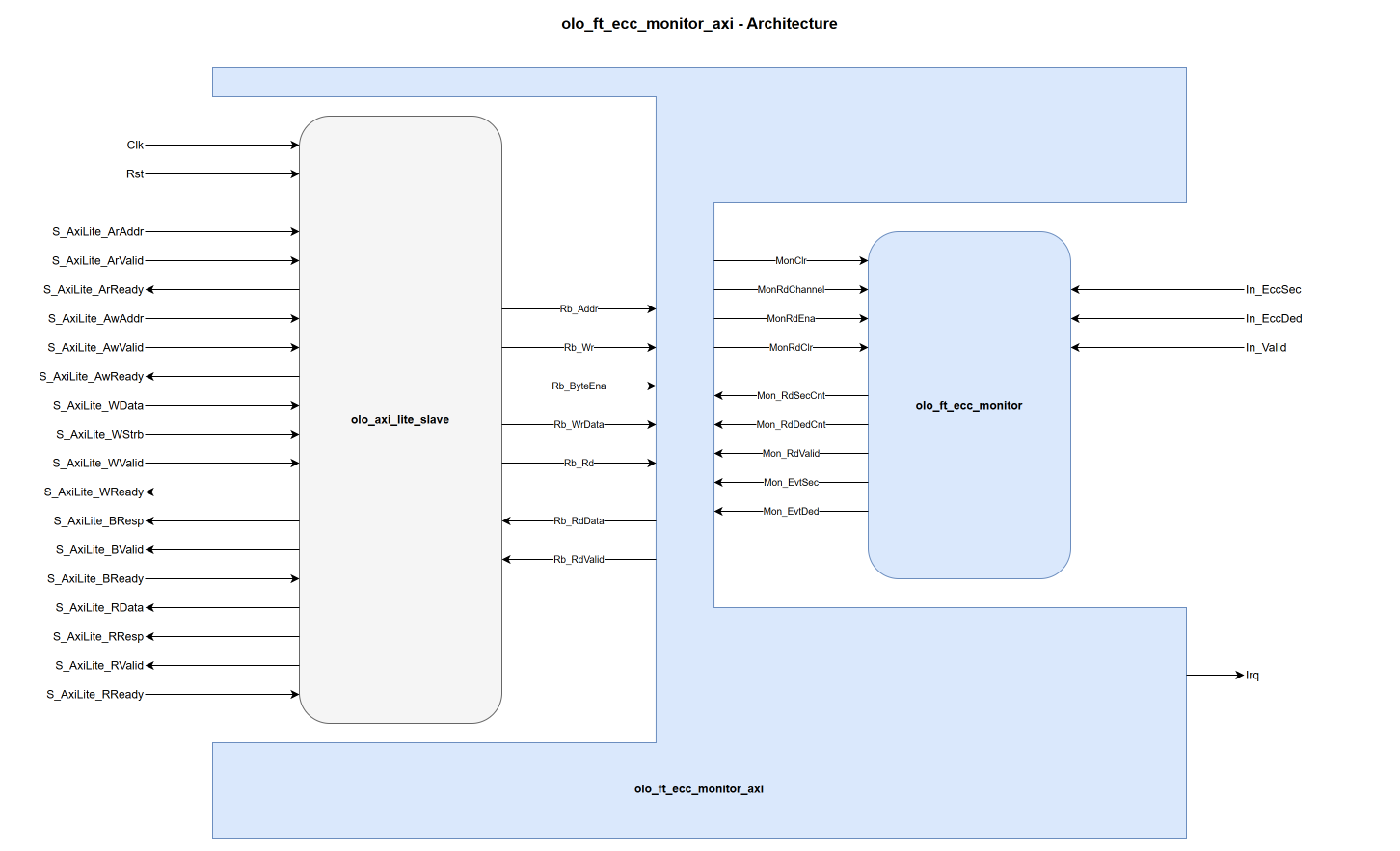
The composition is olo_axi_lite_slave (AXI4-Lite protocol handling, register-bus conversion) plus a small register-decode process plus the olo_ft_ecc_monitor core. Counter reads go through the core's read port, so there is exactly one copy of every counter (no shadow registers). On the internal register bus, the fixed registers respond within one clock cycle and counter reads within three (decode, core read latency, response), both far below ReadTimeoutClks_g. The per-channel write-to-clear reuses the core's atomic read-and-clear mechanism, so the no-lost-events guarantee of the core carries over to the register interface. The only state the wrapper adds is the interrupt block (two latch bits, two enable bits) and the response registers; everything remains in flip-flops coverable by vendor TMR, and like the core, the wrapper has no error-injection ports (no codeword inside).
The core's DedSticky output is not exposed through the register map: per-channel DED visibility comes from the counter words and the DED interrupt. The port remains available on olo_ft_ecc_monitor for direct use in fabric-side safing logic. Note that CLR_ALL and the per-channel write-to-clear also clear the corresponding DedSticky flags of the core.
Usage Example
A monitor collecting from a scrub RAM (countable pulses, qualifier left at '1') and a FIFO (data-aligned flags, qualified with the handshake):
-- Channel 0: scrub status pulses are always qualified
In_EccSec(0) <= Scrub_EccSec;
In_EccDed(0) <= Scrub_EccDed;
In_Valid(0)  <= '1';

-- Channel 1: FIFO output flags are only valid on an accepted beat
In_EccSec(1) <= Fifo_OutEccSec;
In_EccDed(1) <= Fifo_OutEccDed;
In_Valid(1)  <= Fifo_OutValid and Fifo_OutReady;
Note that In_Valid must be driven completely as soon as it is connected at all; the all-'1' default applies only to a fully unconnected port.
For sources in other clock domains, see olo_ft_ecc_monitor - Connecting Sources.
Further Information
- See Open Logic Fault-Tolerance Principles - Constraints That Apply Across the Area for the constraints that apply across the ft area.