olo_base_latency_comp
Status Information
VHDL Source: olo_base_latency_comp
Description
This component does compensate the latency of a processing element by delaying data that bypasses the processing element by delaying the bypass data-path. This is visualized by the figure below. In the setup depicted in the figure, Filter Data and Bypass Data arriving on the input in the same cycle reaches the output in the same cycle.
Note that the block only works for processing elements that do not change the sample rate (i.e one output sample is produced for each input sample).
Input samples are shifted into the delay when both In_Valid and In_Ready are high. Output samples are considered as read when both Out_Valid and Out_Ready are high.
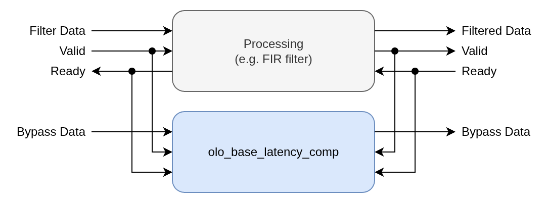
The data going through the olo_base_latency_comp entity may be the same data that goes through the processing element or it may be different data (e.g. metadata associated with the data going through the processing element).
The olo_base_latency_comp entity is non-intrusive in the sense that it does not modify the handshaking signals. It does simply delay the data and executes extensive checking and error reporting in case of failure to compensate the latency.
The entity has two modes of operation:
- DYNAMIC
- The latency is adjusted dynamically to match the latency of the processing element.
- This mode allows to write code that works even if the latency of the processing element changes (e.g. when generics are changed or additional pipeline stages are added).
- This mode is most versatile and even works if the latency is non-constant
- FIXED_CYCLES
- The latency is fixed to a constant number of clock cycles specified by the generic Latency_g.
- This mode requires the latency of the processing element to be known and fixed.
- This mode does allow to process one sample per clock-cycle
Main aim of this entity is to simplify the creation of maintainable code that works independently of smaller changes in the main processing element. The entity also increases maintainability by reporting errors in cases where the latency cannot be compensated successfully.
DYNAMIC Mode
DYNAMIC mode has the advantage that the exact delay does not have to be known at the cost of increased LUT usage for implementing the underlying FIFO. This mode also can be used with processing elements that have non-constant latency.
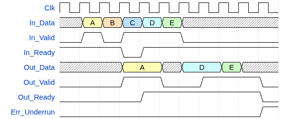
Notes to the figure:
- Samples B and C are ignored because either In_Valid is low or In_Ready is low.
- Non-constant latency is handled by only providing the next sample after the last one has been read (both Out_Valid and Out_Ready high).
- After sample E an underrun is detected because a sample is read but none was written.
FIXED_CYCLES Mode
FIXED_CYCLES mode has the advantage that the exact delay is known and fixed, which can reduce LUT usage compared to the DYNAMIC mode. This mode requires the latency of the processing element to be known and constant.
An overrun error is reported only when the last sample was not read before the next sample arrives at the output. Limited backpressure (In_Ready low) is supported as long as the output is accepted before the next sample arrives.
An underrun is detected if an output sample is read when no sample is present from the delay line.
Below figure depicts Latency_g=3.
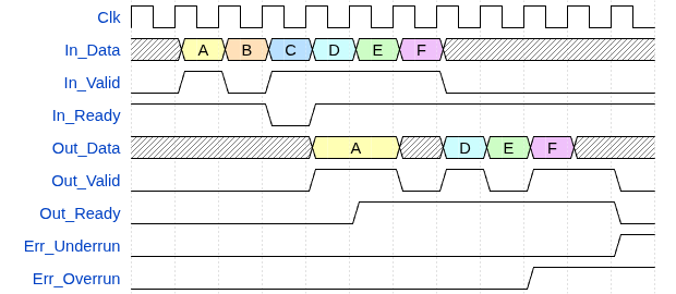
Notes to the figure:
- Samples B and C are ignored because either In_Valid is low or In_Ready is low.
- As long as no new sample arrives, handshaking is tolerated without error (see sample A)
- After sample F an underrun is detected because a sample is read but none was written.
- After sample E an overrun is detected because E was not read before F arrived.
Generics
| Name | Type | Default | Description |
|---|---|---|---|
| Width_g | positive | - | Data width |
| Mode_g | string | "DYNAMIC" | Operation mode. Possible values are: "DYNAMIC": Dynamically adjust latency to match the processing element "FIXED_CYCLES": Fixed latency in clock cycles as specified by Latency_g |
| Latency_g | positive | 30 | The meaning of this generic is as follows, depending on the value of Mode_g: "DYNAMIC": Maximum latency in beats/samples "FIXED_CYCLES": Exact latency in clock cycles Range 2 ... 2^31-1 |
| AssertsDisable_g | boolean | false | Disable assertion reports (errors/warnings) for under- and overflow (can be used if this is expected) |
| AssertsName_g | string | "No Name" | Name used in assertion reports to identify the instance of the entity |
| RamBehavior_g | string | "RBW" | "RBW" = read-before-write, "WBR" = write-before-read For details refer to the description in olo_base_ram_sdp. This generic only plays a role for very large Latency_g values that map into BRAMs |
| Resource_g | string | "AUTO" | Through this generic, the delay implementation for _Mode_g="FIXED_CYCLES" can be controlled.: see olo_base_delay for details |
| RamStyle_g | string | "auto" | Through this generic, the exact resource to use for implementation can be controlled for Mode_g="FIXED_CYCLES" and _Resource_g="BLOCK" and for Mode_g="DYNAMIC". For details refer to the description in olo_base_ram_sdp. |
For technologies that do not support shift-register implementation in LUTs and Mode_g="FIXED_CYCLES", _Resource_g="BLOCK" often is more resource efficient even for moderate delay values to avoid a large number of FFs (given that blockram utilization is not critical).
Interfaces
Control
| Name | In/Out | Length | Default | Description |
|---|---|---|---|---|
| Clk | in | 1 | - | Clock |
| Rst | in | 1 | - | Reset input (high-active, synchronous to Clk) |
Input Data
| Name | In/Out | Length | Default | Description |
|---|---|---|---|---|
| In_Data | in | Width_g | - | Input data |
| In_Valid | in | 1 | '1' | AXI4-Stream handshaking signal from the processing element |
| In_Ready | in | 1 | '1' | AXI4-Stream handshaking signal from the processing element |
Note: The direction of In_Ready is input in this case because the entity is non-intrusive and does not modify the handshaking signals.
Output Data
| Name | In/Out | Length | Default | Description |
|---|---|---|---|---|
| Out_Data | out | Width_g | N/A | Output data |
| Out_Valid | in | 1 | '1' | AXI4-Stream handshaking signal from the processing element |
| Out_Ready | in | 1 | '1' | AXI4-Stream handshaking signal from the processing element |
Note: The direction of Out_Valid is input in this case because the entity is non-intrusive and does not modify the handshaking signals.
Error Outputs
| Name | In/Out | Length | Default | Description |
|---|---|---|---|---|
| Err_Overrun | out | 1 | N/A | Overrun error signal indicating input data was lost due to backpressure |
| Err_Underrun | out | 1 | N/A | Underrun error signal indicating output data was not present when expected |
Error outputs stay asserted once they are set (sticky) until the next reset.
Architecture
DYNAMIC Mode
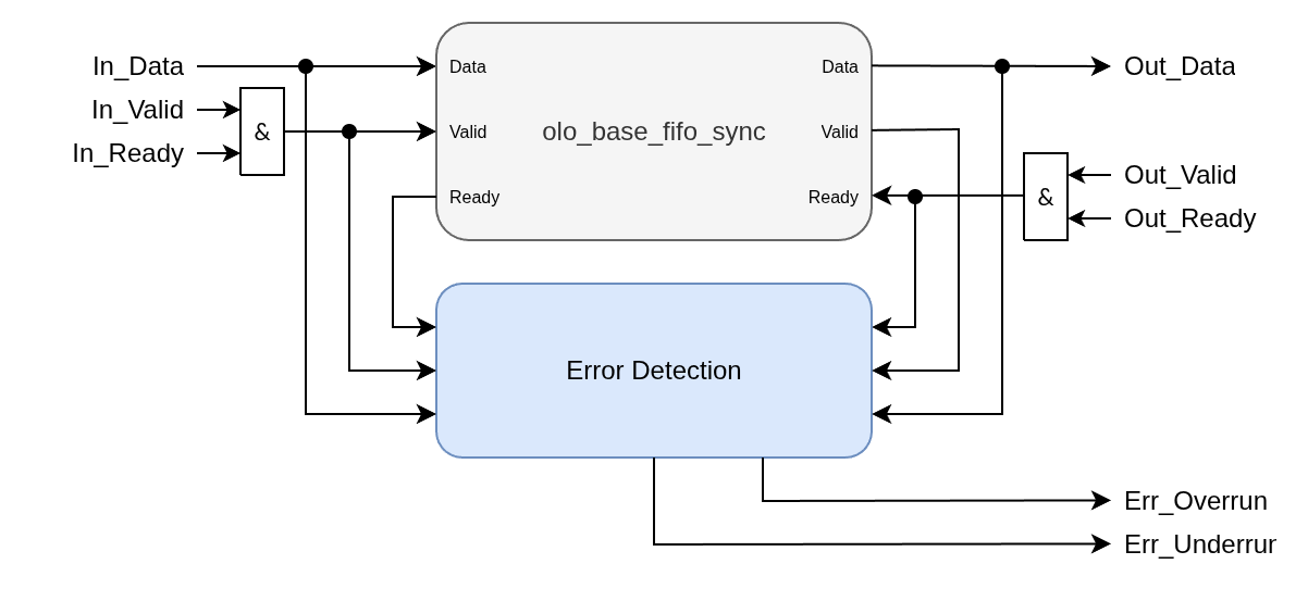
In DYNAMIC mode the latency is adjusted dynamically using an internal FIFO. Note that for implementation reasons, the FIFO depth is Latency_g + 2. This may be considered to most efficiently parametrize the entity.
FIXED_CYCLES Mode
In FIXED_CYCLES mode the latency is compensated through a fixed delay line and handshaking tolerance is added through a single storage state at the output.
To detect overruns, the validity of samples (In_Valid and In_Ready both high) is shifted through the delay line together with the data.
