olo_fix_cic_dec_par_tdm
Status Information
VHDL Source: olo_fix_cic_dec_par_tdm.vhd
Bit-true Model: olo_fix_cic_dec.py
Description
This entity implements a CIC decimator of configurable order. I takes one or multiple channels in parallel on the input side and produces a time-division-multiplexed output stream with the same number of channels. The decimation ratio can either be runtime configurable or fixed (i.e. compile-time configured).
Because the input side is parallel, the filter supports one sample per clock cycle per channel on the input side. So for all channels the input sample rate can be up to the clock frequency.
For details about the fixed-point number format used in Open Logic, refer to the fixed point principles.
The modes can be summarized as follows:
- Fixed ratio mode:
- FixedRatio_g = true
- The configuration ports Cfg_xxx are ignored and can be left unconnected.
- The CIC filter calculates all shift and gain correction factors internally
- Configurable ratio mode:
- FixedRatio_g = false
- The user is responsible for applying the correct values to the configuration ports Cfg_xxx (see formulas in Runtime Ratio Configuration).
- The ratio is only allowed to be changed when the CIC is in reset (i.e. Rst=1_).
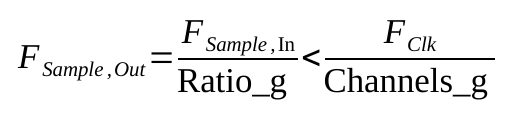
Due to the parallel input and TDM output handling, the user is responsible for ensuring that the output bandwidth is not exceeding the bandwidth required based on the input sample rate and the decimation ratio. Below condition always must hold true:
CIC Gain Handling
CIC filers have an inherent gain given by the formula below.

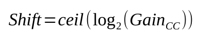
This gain is corrected into the range 0.5 to 1.0 by a bitshift
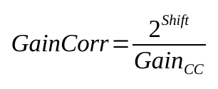
For GainCorrCoefFmt_g != "NONE", the gain is fine-corrected using a multiplier to exactly 1.0:
If the gain correction is disabled (i.e. GainCorrCoefFmt_g = "NONE"_), the multiplier is bypassed and only the bitshift is applied to correct the gain into the range 0.5 to 1.0:
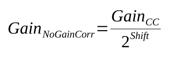
For CIC gains that are a power of two, the gain correction can be disabled because the gain is already exactly 1.0 after the bitshift. It is also possible to disable the gain correction for non-power-of-two gains and implement the fine correction externally.
Latency
This block does change the sample-rate. Because not every input sample produces an output sample, the latency is not fixed and therefore not documented in detail.
Generics
| Name | Type | Default | Description |
|---|---|---|---|
| Channels_g | positive | 1 | Number of TDM channels |
| Order_g | positive | - | CIC order (number of integrator and comb stages) Range 2 ... 32 |
| Ratio_g | positive | - | Fixed ratio mode: Decimation ratio Configurable ratio mode: Maximum decimation ratio |
| FixedRatio_g | boolean | true | Implement fixed ratio (true) or configurable ratio (false) |
| DiffDelay_g | positive | 1 | Differential delay of comb section (usually 1 or 2) |
| InFmt_g | string | - | Input data format String representation of an en_cl_fix Format_t |
| OutFmt_g | string | - | Output data format String representation of an en_cl_fix Format_t |
| GainCorrCoefFmt_g | string | "(0,1,16)" | Gain correction coefficient format Must be (0,1,x) String representation of an en_cl_fix Format_t. To disable the internal gain compensation, choose "NONE" |
| Round_g | string | "NonSymPos_s" | Rounding mode String representation of an en_cl_fix FixRound_t. |
| Saturate_g | string | "Warn_s" | Saturation mode String representation of an en_cl_fix FixSaturate_t. |
| RamBehavior_g | string | "RBW" | Resource control for accumulator/differentiator delay lines mapped to RAM. Normally not used except for large Channels_g "RBW" = read-before-write, "WBR" = write-before-read For details refer to the description in olo_base_ram_sdp. |
| Resource_g | string | "AUTO" | Resource control for accumulator/differentiator delay lines. Normally not used except for large Channels_g see olo_base_delay for details |
| RamStyle_g | string | "auto" | Resource control for accumulator/differentiator delay lines mapped to RAM. Normally not used except for large Channels_g For details refer to the description in olo_base_ram_sdp. |
When gain correction is disable (i.e. GainCorrCoefFmt_g = "NONE"_), the gain is corrected into the range 0.5 to 1.0 by shifting the output. Only the fine correction to exaxtly 1.0 using a multiplier is disabled in this case.
Interfaces
Control
| Name | In/Out | Length | Default | Description |
|---|---|---|---|---|
| Clk | in | 1 | - | Clock |
| Rst | in | 1 | - | Reset (synchronous, active high) |
Runtime Ratio Configuration
| Name | In/Out | Length | Default | Description |
|---|---|---|---|---|
| Cfg_Ratio | in | log2ceil(Ratio_g) | - | Configured decimation ratio minus 1 (only used if FixedRatio_g=false) Example: CfgRatio=3 -> Ratio = 4 |
| Cfg_Shift | in | 8 | - | Configured bit shift (only used if FixedRatio_g=false) Width is limited to 8 bits |
| Cfg_GainCorr | in | width(GainCorrCoefFmt_g) | - | Configured gain correction coefficient (only used if GainCorrCoefFmt_g /= "NONE") |
These ports are only required for FixedRatio_g = false and can be left unconnected otherwise. The user is responsible for applying the correct values to these ports (see formulas above). The ratio is only allowed to be changed when the CIC is in reset (i.e. Rst=1_).
The width of Cfg_Shift is fixed to 8 bits for simplicity reasons. In practice, CICs with more than 255 bits of growth are not paractical anyways because they would require too much resouces and lead to timing issues. Therefore a fixed width of 8 bits is sufficient for all sane use-cases.
The formulas for the values to apply are given in section CIC Gain Handling.
Input Data
| Name | In/Out | Length | Default | Description |
|---|---|---|---|---|
| In_Valid | in | 1 | '1' | Input valid |
| In_Data | in | width(InFmt_g)*Channels_g | - | Input data Channel-0 = In_Data[N-1:0] Channel-1 = In_Data[2*N-1:N] ... |
Output Data
| Name | In/Out | Length | Default | Description |
|---|---|---|---|---|
| Out_Valid | out | 1 | N/A | Output valid |
| Out_Data | out | width(OutFmt_g) | N/A | Output data |
| Out_Last | out | 1 | N/A | TDM frame boundary see TDM Conventions |
Details
General Architecture
The architecture of the CIC decimator is pretty standard and shown in the figure below. Colors denote different implementation options.
- Blue: FixedRatio_g = true (fixed ratio mode)
- Purple: FixedRatio_g = false (configurable ratio mode)
- Orange: GainCorrCoefFmt_g = "NONE"_ (shift-only gain correction)
- Yellow: GainCorrCoefFmt_g != "NONE"_ (multiplier-based gain correction)
The figure shows Order_g = 2 and Channels_g = 3 (10 bit per channel).
 .
.
Important for efficiency is the order of decimation, parallel to TDM conversion and shift. The decimation must happen first in order to ensure the bandwidth of the parallel to TDM converter on the output (TDM) side is as low as possible. Thanks to the shift happening on the TDM side, only one shifter is required for all channels, which is significantly more efficient than shifting before the TDM conversion.
The parameters RamBehavior_g, Resource_g, and RamStyle_g are forwarded to all olo_base_delay instances. They are impoortant only for cases with enough channels to make usage of RAM (distributed or block RAM) for the delay lines attractive.
Note that for FixedRatio_g = false a dynamic shifter is required, which consumes more resources than a fixed shifter for FixedRatio_g = true.
Gain Correction
The gain correction is depicted in detail below. It is important to know that the input to the gain correction multiplier has exactly two bits more than OutFmt_g because this knowledge might be requried to ensure ability to map the gain correction to a single hardware multiplier.
The input to the gain correction multiplier is truncated to the format (OutFmt_g.S, OutFmt_g.I, OutFmt_g.F+2). This value is then multiplied with the gain correction coefficient and rounded/saturated according to the Round_g and Saturate_g_ generics to produce the output in format OutFmt_g.
