olo_fix_fir_dec_ser_chpar
Status Information
VHDL Source: olo_fix_fir_dec_ser_chpar.vhd
Bit-true Model: olo_fix_fir_dec.py
Description
This entity implements a decimating FIR filter for one or more parallel channels. All channel samples are presented at the same time, concatenated into one wide input vector (channel 0 in the least significant bits). All channels share the same coefficient set. The filter taps are computed serially (one tap per clock cycle), using one dedicated multiplier per channel.
Example: A 4 channel, 16 taps FIR filter requires 16 clock cycles to produce one output sample set (one sample for each channel). All four channels are computed in parallel during these 16 cycles.
Note that the filter can also be used non-decimating (ratio=1) and for a single channel (Channels_g = 1).
For details about the fixed-point number format used in Open Logic, refer to the fixed point principles.
The bit-true model and cosimulation are shared with olo_fix_fir_dec_ser_chtdm. The two entities differ only in how the channels are presented (parallel vs. time-division-multiplexed).
Coefficients can be fixed (ROM) or runtime configurable (RAM) with optional readback.
Input Bandwidth Limitation
This entity does not generate backpressure. The serial MAC requires Taps clock cycles to compute one output sample set (all channels are computed in parallel). This calculation is repeated every Ratio input sample sets.
where f_in is the rate of complete input sample sets (one set = one sample per channel, all presented in the same clock cycle). If the input arrives faster than this limit, the filter will stop working correctly.
The second row calculates the number of taps that can be processed with given raio, input rate and clock frequency.
Use olo_base_rate_limit externally to enforce the rate limit.
Latency
This block changes the sample rate. Because not every input sample produces an output sample, the latency is not fixed and is therefore not documented in detail.
Generics
General Generics
| Name | Type | Default | Description |
|---|---|---|---|
| InFmt_g | string | - | Input format String representation of an en_cl_fix FixFormat_t |
| OutFmt_g | string | - | Output format String representation of an en_cl_fix FixFormat_t |
| CoefFmt_g | string | - | Coefficient format String representation of an en_cl_fix FixFormat_t |
| Channels_g | positive | - | Number of parallel channels (1 or more) |
| MaxRatio_g | positive | - | Maximum decimation ratio |
| MaxTaps_g | positive | - | Maximum number of filter taps (must be >= 2) |
| RuntimeCfg_g | boolean | false | true - the active ratio and tap count are taken from the Cfg_Ratio / Cfg_Taps ports. false - they are fixed to MaxRatio_g / MaxTaps_g and the Cfg_... ports are ignored. |
| GuardBits_g | natural | 1 | Number of integer guard bits in the accumulator above OutFmt_g |
| Round_g | string | "Trunc_s" | Rounding mode String representation of an en_cl_fix FixRound_t |
| Saturate_g | string | "Warn_s" | Saturation mode String representation of an en_cl_fix FixSaturate_t |
| MultRegs_g | positive | 1 | Number of pipeline registers in the multipliers |
Coefficient and Data Storage
| Name | Type | Default | Description |
|---|---|---|---|
| CoefInit_g | string | "0.0" | Comma-separated initial coefficient values (real numbers, quantized to CoefFmt_g) Example: "0.3, 0.55, 0.2" see olo_fix_coef_storage |
| CoefStorageType_g | string | "ROM" | Coefficient storage type: "ROM" (fixed) or "RAM" (runtime-updateable) see olo_fix_coef_storage |
| CoefRamReadback_g | boolean | false | Enable coefficient readback via Coef_Rd_... ports (RAM mode only) see olo_fix_coef_storage |
| CoefRamBehavior_g | string | "RBW" | Coefficient RAM behavior: "RBW" = read-before-write, "WBR" = write-before-read see olo_fix_coef_storage |
| CoefMemStyle_g | string | "auto" | Synthesis attribute for coefficient memory style (e.g. "block", "distributed") see olo_fix_coef_storage |
| DataRamBehavior_g | string | "RBW" | Data RAM behavior: "RBW" = read-before-write, "WBR" = write-before-read see olo_base_ram_sdp |
| DataMemStyle_g | string | "auto" | Synthesis attribute for data RAM style (e.g. "block", "distributed") see olo_base_ram_sdp |
Interfaces
Control
| Name | In/Out | Length | Default | Description |
|---|---|---|---|---|
| Clk | in | 1 | - | Clock |
| Rst | in | 1 | - | Reset (synchronous, active high) |
Runtime Configuration
| Name | In/Out | Length | Default | Description |
|---|---|---|---|---|
| Cfg_Ratio | in | log2ceil(MaxRatio_g) | MaxRatio_g-1 | Decimation ratio minus 1 (1 = ratio 2, 7 = ratio 8). |
| Cfg_Taps | in | log2ceil(MaxTaps_g) | MaxTaps_g-1 | Active tap count minus 1 (1 = 2 taps). A single tap (value 0) is not supported. |
Both ports have safe defaults (maximum ratio and tap count) and are only used when RuntimeCfg_g = true. They can be left unconnected to use the fixed maximum values. Change only when Rst = '1'.
Coefficient Configuration
| Name | In/Out | Length | Default | Description |
|---|---|---|---|---|
| Coef_Addr | in | log2ceil(MaxTaps_g) | 0 | Coefficient address for read/write |
| Coef_WrEna | in | 1 | '0' | Coefficient write enable (RAM mode only) |
| Coef_WrData | in | width(CoefFmt_g) | 0 | Coefficient write data (RAM mode only) |
| Coef_RdEna | in | 1 | '0' | Coefficient read enable (RAM readback mode only) |
| Coef_RdData | out | width(CoefFmt_g) | N/A | Coefficient read data (0 in ROM mode) |
| Coef_RdValid | out | 1 | N/A | Coefficient read valid (0 in ROM mode) |
All Coef_* ports have safe defaults and can be left unconnected in ROM mode or when coefficient updates are not needed.
Input Data
| Name | In/Out | Length | Default | Description |
|---|---|---|---|---|
| In_Valid | in | 1 | - | Input valid (all channels valid together) |
| In_Data | in | width(InFmt_g) x Channels_g | - | Input data (channels concatenated, channel 0 in the least significant bits) |
Output Data
| Name | In/Out | Length | Default | Description |
|---|---|---|---|---|
| Out_Valid | out | 1 | N/A | Output valid (all channels valid together) |
| Out_Data | out | width(OutFmt_g) x Channels_g | N/A | Output data (channels concatenated, channel 0 in the least significant bits) |
Details
Example Instantiation
The example below shows the simplest possible instantiation: fixed coefficients stored in ROM, a fixed tap count and a fixed decimation ratio. The ratio and tap count are fixed by setting MaxRatio_g / MaxTaps_g to the desired values and leaving Cfg_Ratio / Cfg_Taps unconnected (they then default to those maxima). All coefficient configuration ports are omitted as well.
i_fir : entity olo.olo_fix_fir_dec_ser_chpar
    generic map (
        -- Formats
        InFmt_g    => "(1,0,15)",
        OutFmt_g   => "(1,0,15)",
        CoefFmt_g  => "(1,0,17)",
        -- Filter parameters (ratio and taps are fixed to these maximum values)
        Channels_g => 4,
        MaxRatio_g => 4,
        MaxTaps_g  => 3,
        -- Fixed coefficients stored in ROM
        CoefInit_g => "0.25, 0.5, 0.25"
    )
    port map (
        Clk       => Clk,
        Rst       => Rst,
        In_Valid  => In_Valid,
        In_Data   => In_Data,
        Out_Valid => Out_Valid,
        Out_Data  => Out_Data
    );
Architecture
Below figure illustrates the architecture of the filter:
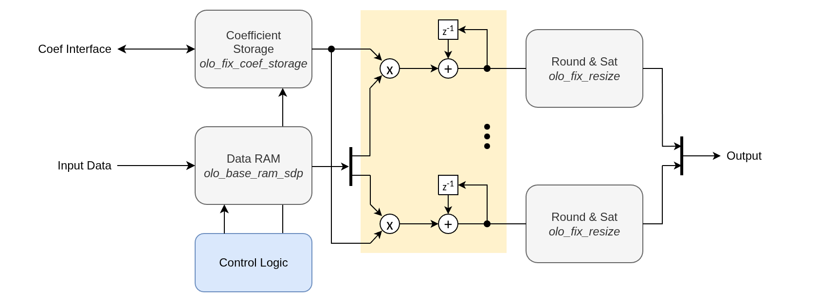
All channel data is stored in a single simple dual-port RAM (olo_base_ram_sdp). Because the channels are processed in parallel, all channel samples of a given time step are stored in one wide RAM word (width = width(InFmt_g) x Channels_g).
Coefficients are stored in a dedicated olo_fix_coef_storage instance (ROM or RAM depending on CoefStorageType_g) and are shared by all channels. As a result the coefficieent memory size is independent of the number of channels.
There is one multiplier (olo_fix_mult) and one output resize (olo_fix_resize) per channel (yellow). All multipliers use the same coefficient and the same tap address, they only differ in their data input from the data RAM.
Because the data is written into the RAM as it arrives and is read out only when processed, the input may be bursty or have a constant rate. Both work fine.
Startup Behavior
At startup the data RAM may contain leftover data from before the reset. The filter replaces RAM reads of locations not yet written with zeros. This matches the Python model, which initializes its delay line to zero, ensuring bit-true agreement from the first output sample.
Coefficient Format
The accumulator operates at full multiply precision:
- MultFmt = (max(In.S, Coef.S), In.I + Coef.I, In.F + Coef.F)
- AccuFmt = (1, Out.I + GuardBits_g, In.F + Coef.F) (GuardBits_g guard bits above output)
Choosing OutFmt.I or GuardBits_g too small risks accumulator overflow. Ensure max_sum_of_products <= 2^(OutFmt.I + GuardBits_g) - 1 LSB.
Accumulator Guard Bits
The accumulator carries GuardBits_g integer guard bits above OutFmt_g (AccuFmt.I = OutFmt.I + GuardBits_g). These bits allow the sum of products to grow beyond the output range during the accumulation without overflowing. With the default of one guard bit, intermediate results of up to twice the OutFmt_g maximum are supported. The user is responsible for choosing GuardBits_g, the coefficients and the formats such that the accumulator does not overflow; otherwise the number of guard bits or the output format must be increased.
Runtime Configuration
The Cfg_Ratio and Cfg_Taps ports are only evaluated when RuntimeCfg_g = true. In that case they must only be changed while Rst = '1'; changing them during operation produces undefined behavior. When RuntimeCfg_g = false (default) the ports are ignored and the filter uses fixed MaxRatio_g / MaxTaps_g values.
A single-tap filter (Cfg_Taps = 0) is not supported. The minimum tap count is 2.