olo_fix_cordic_vect
Status Information
VHDL Source: olo_fix_cordic_vect
Bit-true Model: olo_fix_cordic_vect
Description
Overview
This entity implements the vectoring CORDIC algorithm. This algorithm is usually used to convert from the cartesian to the polar coordinate system, i.e. to calculate the magnitude and angle of a vector given by its X and Y (or I and Q) components.
The algorithm can be implemented in two different modes:
- SERIAL
- Iterations are executed one after the other
- A new sample can be accepted every Iterations_g clock cycles
- Lowest possible resource usage
- PIPELINED
- Iterations are implemented in individual pipeline stages
- Every clock cycle a new sample can be accepted
- Highest possible throughput
For details about the fixed-point number format used in Open Logic, refer to the fixed point principles.
Gain Compensation
The CORDIC algorithm has an inherent gain that depends on the number of iterations. This gain can optionally be compensated directly within the olo_fix_cordic_vect entity. The internal gain compensation works most efficiently if the internal format IntXyFmt_g fits into one multiplier of the target device.
Alternatively, the user may choose to do the gain compensation outside of the entity, e.g. by using an olo_fix_mult entity after the CORDIC. For this the gain factor must be known, hence the formula is given below:
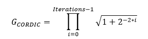
Note that depending on the application the gain compensation may be omitted completely. Therefore it is optional and can be controlled through the generic GainCorrCoefFmt_g.
Latency
The latency of the entity depends on several factors and can best be determined in the simulation.
Note: Latency is not guaranteed to be constant across different version. It's therefore best to design user logic to be independent of the latency of this block (e.g. through olo_base_latency_comp).
In the current version the latency can be approximated as follows:
- Mode_g = "PIPELINED" with gain correction: Latency = 6 + Iterations_g
- Mode_g = "PIPELINED" without gain correction (GainCorrCoefFmt_g = "NONE"): Latency = 5 + Iterations_g
- Mode_g = "SERIAL" with gain correction: Latency = 5 + Iterations_g
- Mode_g = "SERIAL" without gain correction (GainCorrCoefFmt_g = "NONE"): Latency = 4 + Iterations_g
Generics
| Name | Type | Default | Description |
|---|---|---|---|
| InFmt_g | string | - | Input data format Must be (1,x,y) String representation of an en_cl_fix Format_t (e.g. "(1,1,15)") |
| OutMagFmt_g | string | - | Output magnitude format Must be (0,x,y) String representation of an en_cl_fix Format_t (e.g. "(0,1,15)") |
| OutAngFmt_g | string | - | Output angle format Must be (0,0,x) String representation of an en_cl_fix Format_t (e.g. "(0,0,15)") |
| IntXyFmt_g | string | "AUTO" | Internal format for X/Y values. With "AUTO" the format is chosen automatically. For manual control, specify a string representation of a signed en_cl_fix Format_t (e.g. "(1,1,15)"). Refer to Format Considerations for details |
| IntAngFmt_g | string | "AUTO" | Internal format for angles With "AUTO" the format is chosen automatically. For manual control, specify a string representation of a (1,-1,x) en_cl_fix Format_t (e.g. "(1,-1,15)"). Refer to Format Considerations for details |
| Iterations_g | positive | 16 | Number of CORDIC iterations. Range: 3 .. 32 Refer to Format Considerations for details |
| Mode_g | string | "PIPELINED" | CORDIC operation mode "SERIAL": one iteration per clock cycle "PIPELINED": Pipelined mode (one sample per clock cycle) |
| GainCorrCoefFmt_g | string | "(0,0,17)" | Format of the gain correction coefficient, specify a string representation of a signed en_cl_fix Format_t (e.g. "(1,1,15)"). Refer to Format Considerations. To disable the internal gain compensation, choose "NONE" |
| Round_g | string | "Trunc_s" | Rounding mode String representation of an en_cl_fix FixRound_t. |
| Saturate_g | string | "Warn_s" | Saturation mode String representation of an en_cl_fix FixSaturate_t. |
Interfaces
Control
| Name | In/Out | Length | Default | Description |
|---|---|---|---|---|
| Clk | in | 1 | - | Clock |
| Rst | in | 1 | - | Reset input (high-active, synchronous to Clk) |
Input Data
| Name | In/Out | Length | Default | Description |
|---|---|---|---|---|
| In_I | in | width(InFmt_g) | - | In-phase/real part of input data Format: InFmt_g |
| In_Q | in | width(InFmt_g) | - | Quadrature/imaginary part of input data Format: InFmt_g |
| In_Valid | in | 1 | '1' | AXI4-Stream handshaking signal for In_I and In_Q |
| In_Ready | out | 1 | N/A | AXI4-Stream ready signal for In_I and In_Q Used in "SERIAL" mode to signal when a new input sample is taken |
Output Data
| Name | In/Out | Length | Default | Description |
|---|---|---|---|---|
| Out_Mag | out | width(OutMagFmt_g) | N/A | Output magnitude Format OutMagFmt_g |
| Out_Ang | out | width(OutAngFmt_g) | N/A | Output angle, Normalized units (1.0 = 360° = 2*PI) Format OutAngFmt_g |
| Out_Valid | out | 1 | N/A | AXI4-Stream handshaking signal for Out_Mag and Out_Ang |
Note The output interface does not implement backpressure (Ready). If backpressure is required, the user ideally implements it over the whole processing chain using olo_base_flowctrl_handler.
Detail
Format Considerations
IntXyFmt_g
The format for internal calculation of X and Y components must be signed.
The more fractional bits are used, the more precise the calculation gets. Usually a few more fractional bits than in OutMagFmt_g and OutAngFmt_g are required.
The number of integer bits must be chosen to ensure that no overflows happen during calculation. For inputs in the form (1,0,x) that are always within the unit circle, (1,1,y) can be used. For inputs in the form (1,0,x) that can contain arbitrary values for X and Y, (1,2,y) can be used.
Optimization is best performed based on the bit-true python model.
For "AUTO" mode, the internal format is chosen as follows:
- Sign bit: yes
- Integer bits: InFmt_g.I + 2
- Fractional bits: max(OutMagFmt_g.F, OutAngFmt_g.F-InFmt_g.I) + 4
GainCorrCoefFmt_g
For optimal absolute precision, the gain correction coefficient shall have at least the same number of fractional bits as OutMagFmt_g.
In many cases the absolute precision is secondary and only the relative precision matters. In such cases the number of bits can be reduced to save resources. Because all samples receive the same gain correction, any errors in the correction factor will not impact the relative precision between samples.
IntAngFmt_g
Internal calculation format for angles (must be signed) and have -1 integer bits (because only one quadrant is used, angles 0...0.25 but the full range (incl. the 0.25 exactly) must be representable).
The more fractional bits, the more precise the calculation gets. Usually a few more bits than in OutAngFmt_g are required.
Optimization is best performed based on the bit-true python model.
For "AUTO" mode, the internal format is chosen as follows:
- Sign bit: yes
- Integer bits: -1
- Fractional bits: OutAngFmt_g.F + 3
Iterations_g
More iterations lead to more precise results. A good starting point is one iteration per bit in the output format.
Optimization is best performed based on the bit-true python model.
Architecture
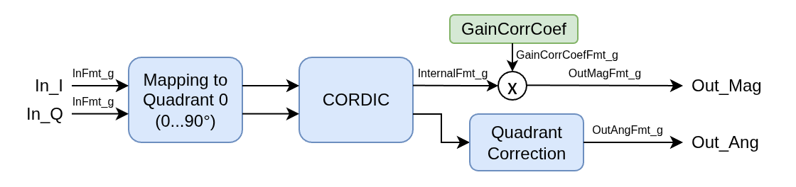
The figure below shows the implementation of the vectoring CORDIC. The algorithm only works correctly in quadrant zero (where I and Q are positive). Therefore the input is mapped into this quadrant by sign swapping and the effect of this mapping is compensated at the output.